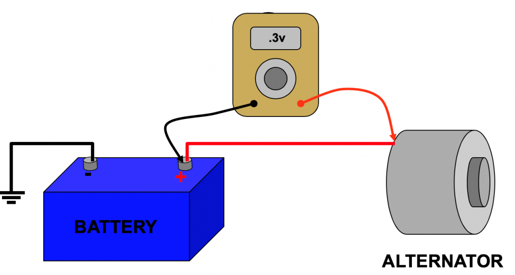
Understanding your car issues can be quite tricky. However, learning the basics of diagnostics in terms of Ohm’s law can make troubleshooting your vehicle problems interesting. Simply put, Ohm’s law can help you explain the cause of the electrical fault your car may be having.
In this post, you’ll learn what Ohm’s law is; and how this principle can be used in your automobile diagnostics testing.
So, what is Ohm’s law?
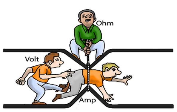
Ohm’s law describes the relationship between the three characteristics of the electrical circuit: the electron flow, the resistance to flow in the wire or other conductor, and the voltage. The law states that the current through a conductor between two points is directly proportional to the voltage across the two points.
This law explains why some circuits work fine, while others have issues. For instance, a bulb that provides illumination that is below par may have a problem that has been caused by excessive resistance in the electrical circuit. Consequently, using Ohm’s law can help us predict and explain what happens in this kind of electrical system. Based on what we know about this law, when an electrical circuit does not function as designed, the problem is typically excessive resistance.
Ideally, when a system is functioning properly, it should take 1 volt to push 1 amp thru 1 ohm (Fig. 1-1) of resistance. So with Ohm’s law, if you know two of the three parameters in the equation, you can figure out the value of the missing one. For example, if you know the volts and the amps, you can deduce the value of the resistance flowing through the circuit.
Now that you know what Ohm’s law is, why is this law important in diagnosing automobiles?
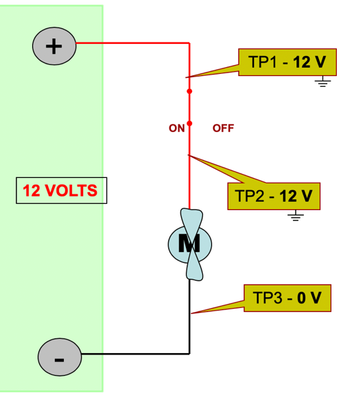
In an automobile system with a 12-volt battery, is expected that if the battery is positive and you run it through an electrical circuit, by the time it goes through the load (motor, light bulb, etc.) and reaches the negative battery post to complete the circuit, it will be down to zero volts.
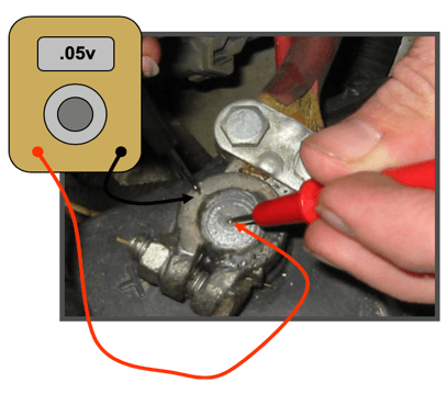
This concept is applicable when carrying out the voltage drop testing. This testing method is one of the best ways to find an electrical fault in a vehicle. This is based on the premise that the voltage drops as it travels through the circuit, so you can tell where it’s being used simply by measuring the voltage at different points in the circuit.
To understand this concept better, let’s take a look at how a car travels on a defined road where the road is the electrical circuit and gas consumed by the car is the voltage. If the vehicle that leaves the positive battery post with just enough gas to work the load and gets to the negative battery post. By the time the car reaches the negative battery post, it would have run out of gas. As stated earlier, if the gas is the voltage and the car starts at its highest level at the positive battery terminal, it means that it will end up at zero when it reaches the negative battery terminal.
Now, let’s take a look an interesting scenario, if somewhere in the circuit, the car takes a detour and goes down a different road and decides not to take the road (circuit) all the way back to battery negative. Well, in this case, we call it a short circuit. And when this happens, it is possible to end up with a blown fuse or a part of the electrical system that melts or burns up. This is as a result of the unrestricted amp flow that occurs during a short circuit.
Here’s another scenario, what if the car encounters an obstruction in the road (circuit) and we expend more gas getting through the obstruction on our way back to battery negative. Theoretically, the car can still make it back to battery negative, but since we expended so much fuel (voltage) getting through the resistance and the load, there’s hardly any fuel left to do any work.
Often times, this happens when we have increased resistance in an automotive electric circuit. For example, if it is a window motor that is responsible for the increased resistance, the window motor will still work; the only problem is it will work very slowly. The effect of this increased resistance is that when we had to go through to get back to battery negative, we expended a significant amount of fuel (voltage) overcoming the resistance in the circuit. As a result, less fuel (voltage) means there isn’t enough to run the window motor at full capacity.
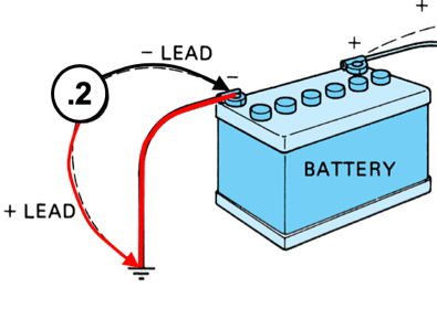
However, with a voltage drop test following the path of the automotive electric circuit, you can detect the part of the circuit where the fuel (voltage) is being used. This is usually seen as the biggest drop across the load of the circuit, which, in the case of the earlier example is the window motor.
Generally, voltage drop is done on a live circuit, this way; you can see the voltage before and after the motor (Fig. 1-2). If the circuit isn’t active, you won’t get any readings.
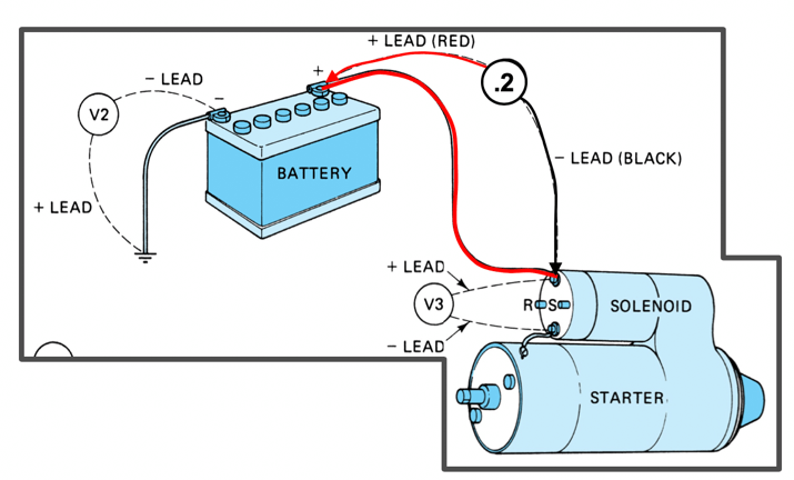
When checking the voltage after running the motor, the voltage should be zero. This can be seen in every electrical circuit according to Ohm’s law. Once you know the circuit, you can detect where the voltage is being expended and this can be done by measuring the voltage at different points in the circuit to understand how the circuit is operating.
So that’s it, voltage drop testing is an excellent way of diagnosing the automotive electric circuits, but you shouldn’t forget the basis of the testing which Ohm’s law is.
